in this guide we have described all details about rotary evaporator or Rotovap
A Rotary Evaporator, also popularly known as a Rotavapor or Rotovap, is a specialized and extremely versatile equipment for chemical processes.
In this Article, we would touch upon the following broad topics:
- Rotary Evaporator Principle
- Rotary Evaporator Construction
- Rotary Evaporator Design Variations
- Rotary Evaporator Applications
- Other Evaporation Alternatives to Rotovap
What is a Rotary Evaporator or Rotovap?
As per name we can understand by seperating two terms one is rotary and second is evaporator
Rotary means rotating movement and Evaporator means evaporation process of some liquid or fluid
Rotary Evaporator Principle
The Evaporator is essentially working on the same principles as a distillation unit i.e. separation of components having different boiling points. However, few special design features make the functioning of the Rotovap unique and versatile.
- Operation under high vacuum of 1 torr, thereby reducing the solvent boiling points under vacuum considerably as compared to the boiling point under atmospheric conditions.
- Constant rotation of Rotary flask results in a thin layer of process media on the inner wall, thereby ensuring uniform heating across the entire mass, and less possibility of bumping.
- The rotation of flask immersed in the bath increases the surface area of evaporation greatly, thereby increasing the speed of distillation.
- The rotation mechanism also makes it suitable for volatile and heat-sensitive process media, wherein the properties can alter if direct high heat is applied for longer time. This is because due to rotation, the process feed is evenly mixed.
- Plug and Play type of construction making it easy to switch the configuration for different applications.
The Rotary Evaporator is normally always operated under high vacuum. The Feed is charged inside the rotary flask from the feed tube made of PTFE.
Ideally, feed up to a maximum of 70–80% capacity of the rotary flask is desired for optimum results. Once the feed is charged, the rotation is started.
Also, the utility circulation in the condenser is started. This rotation action creates a thin film of process feed on the wall of the rotating flask.
Next the heating is started. The rotary evaporator procedure is very crucial for efficient performance. Once the oil in the bath starts heating, and this heat is indirectly passed to the process feed inside the flask.
As the process feed gets heated, the low boiler converts into vapours, and goes up the vapour tube and into the condenser, where the condensate is formed.
This condensate can either be refluxed back into the rotary flask for higher purity applications, or collected in the receiver.
Depending on the design features, a lot of different process possibilities are there, but the basic operating principle essentially remains as indicated above.
How does a vacuum evaporator work (Construction)?
The main components of a Standard Rotary Evaporator are enlisted below:

The water/oil bath is a heated bath which encloses the main rotary flask and is used to indirectly heat the contents of the process.
The bath is usually equipped with electric heaters which can be ATEX-compliant or weather-proof, depending on the application area’s Hazardous Zone Classification.
As a safety feature, the bath is appropriately insulated so that the outside surface is not too hot to touch.
The Rotary Flask is the main component where the process fluid is initially charged, and is made of Borosilicate Glass 3.3 raw material.
The Flask’s construction is of prime importance for the smooth rotation along the central axis.
Our advanced manufacturing techniques ensure that the evaporating flask is rotating perfectly along the central axis, thereby ensuring that the entire surface area comes in contact for the same time with the heating media in bath.
The Mechanical Seal, along with the motor unit connected to the flask is responsible for smooth and leak proof rotation of the flask at a constant speed.
An RTD is placed just above the vapour tube to measure the vapour temperature before it goes into condenser.
The RTD is inserted inside the vapour tube in a glass thermowell. This ensures that the contact parts are strictly Borosilicate Glass 3.3 and PTFE only and the metal tip of PT-100 sensor does not come in direct contact with the process vapour.
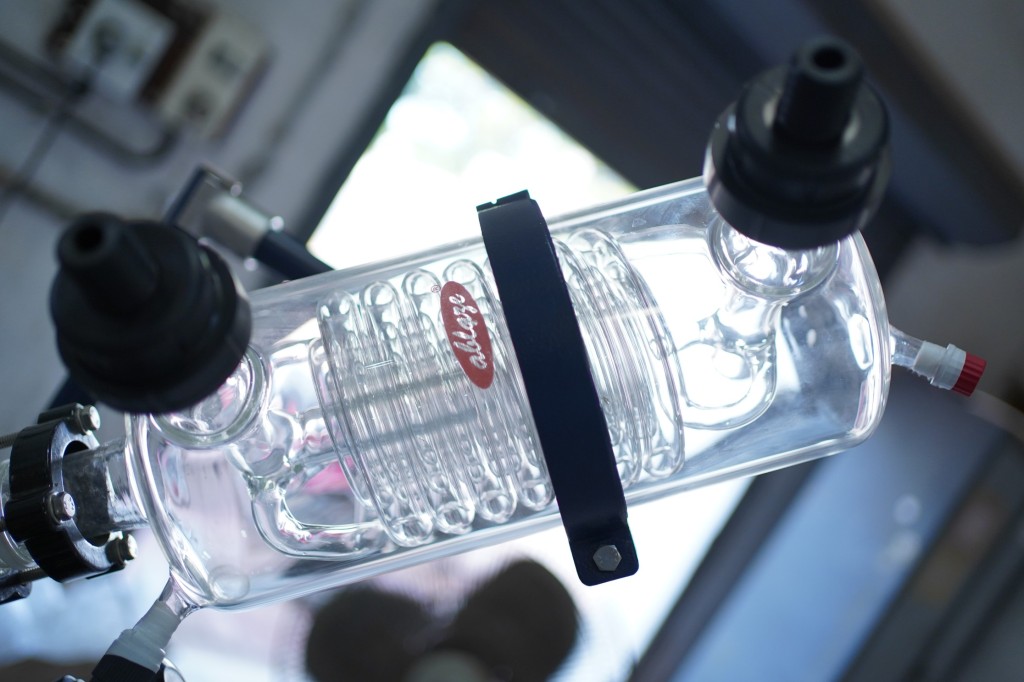
A Shell & Coil type condenser of suitable heat transfer area is chosen so that there is no pressure build-up due to excessive un-condensed vapours.
The condenser is preferably placed in vertical orientation for efficient condensation.
Different configurations with single and double condensers are available depending on the application. As a standard, a single condenser is provided.

A vent is provided at the top of the condenser. This can be used for venting in the case of excessive pressure build-up.
We can also connect the vacuum pump here. Alternatively, the vacuum pump connection can be made at the receiver vent nozzle.
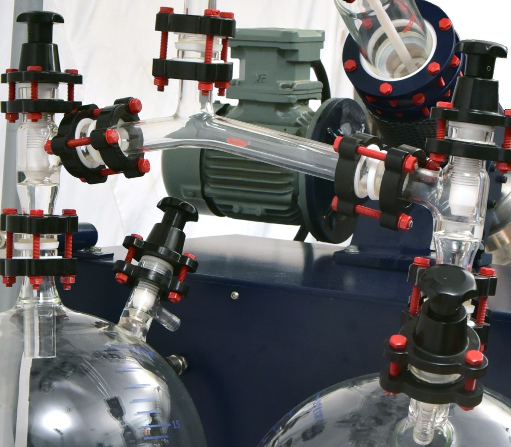
All such vent outlets are equipped with suitable valves with leak-proof PTFE bellow to glass connections.
The vent valve is provided with GL18 thread at the end, where BOLA connectors can be placed and hose pipe connected.
This arrangement provides seamless connection without any leakages.
The Liquid feed is used to feed the process feed into the rotary flask without breaking the process vacuum.
Since the system is already under vacuum, the process feed easily flows into the system.
This valve too is provided with GL thread and BOLA connector. This valve is connected with a PTFE tube which travels throughout the vapour tube, directly into the rotary Flask.
This ensures that the feed does not get carried to the receiver directly along with the vapour or condensate flowing in the vapour tube.
A Product Cooler is essential to cool down the condensate, before moving it to the receiver.
The product cooler is essentially a Shell & Coil type heat exchanger with the process fluid in the coil side and utility in the shell side.
This arrangement ensures rapid cooling in a short time.
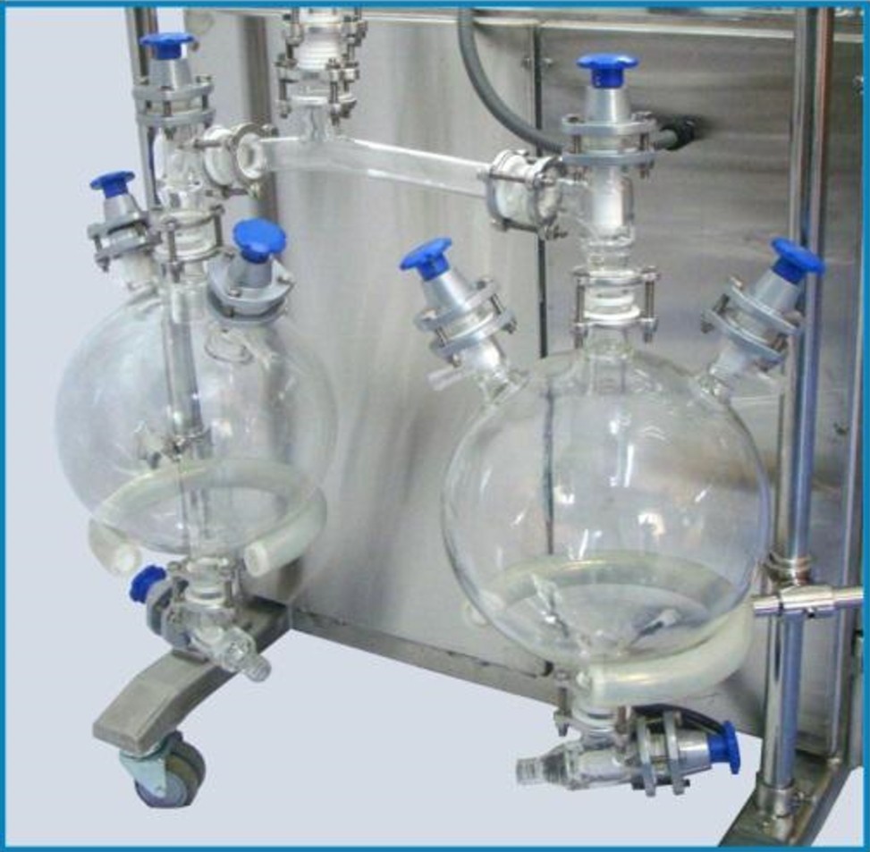
The receivers are spherical vessels with multiple nozzles of a suitable size. The units usually have either one or two receivers, connected in parallel.
The receiving vessel has a short drip tube to ensure that the solvent drops down directly into the vessel and not flow along the walls.
A Control Panel is an integral part of the Rotary Evaporator. This is a highly customized part and Ablaze can offer partial to full automation of the process through the control panel, depending on the client’s process requirement.
As a standard, the basic model has provision for digital display of Bath temperature, Vapour Temperature and RPM of the Rotary Flask. It also has controls to set the desired RPM and the desired Oil Bath Temperature.
In a little advanced models, Vacuum control and monitoring is also provided, wherein the vacuum pump is connected via the panel and the required process vacuum can be set, monitored and controlled directly through the panel.
Further customization and control can be provided, since we have a highly advanced in-house automation team.
The Panel and all the electric components are housed in an ATEX-Compliant Enclosure for operation in hazardous areas.

The Entire Rotary Evaporator System is mounted on a Compact Skid of Stainless Steel where all the components rest and all provided appropriate support to ensure vibration free operation.
This skid itself is mounted on heavy duty Castor Wheels, which can be locked, to provide easy movement of the unit in the plant or lab.
A Safety Lid is placed on the rotary flask as a precaution in case of spillage risk. It is transparent and hence it provides safety without compromising on the reaction visibility.
3. Rotary Evaporator Design Variations
Multiple Design Variations are available in Our Standard Rotary Film Evaporator to suit different process needs. Some of the standard design variations are:
Dual Receivers
This configuration allows continuous drain without breaking the process vacuum. The two receivers are connected in parallel so that at any given point of time, the condensate is being collected in one of them.
Once this receiver is full and needs to be drained out, the valve above it is closed, and the condensate is taken in the second receiver.
This way, the system vacuum is not disturbed during draining.

Dual Condensers
This design is used when immediate condensation of the vapours is required. Two condensers are placed in parallel, and the condensate is directly collected in the receivers.
This ensures 100% solvent recovery. This design can also be modified for continuous operation.
ATEX-Compliant
The Rotavap contains a lot of electric components — two sets of drive (one for rotation and other for bath lifting) and a control panel.
We do understand that a lot of applications require the Rotovap to be used in Zone 0 / 1 / 2 hazardous classified area and hence we have a model with all electrical components and connection which comply to these stringent requirements.
Multiple MOCs
The contact parts with process media are strictly Borosilicate Glass 3.3 and PTFE. However, the couplings, skid etc do not come in contact with the process media and can be offered in various MOCs (Material of Construction) such as Stainless Steel grade 316 or 304, Mild Steel, etc.
The couplings can also be made of Bakelite to provide good resistance to corrosion in case the environment has exposure to corrosive gases. The fasteners can be PTFE coated to improve their life.

4. Rotary Evaporator Applications
The wide array of applications where a rotovap can be used shows how versatile the equipment is. It finds application in the following processes:
- Distillation (Continuous and Discontinuous)
- Concentration
- Solvent Recycling
- Solvent Evaporation and Recycling
- Reflux Process Reactions
- Component Drying
- Component Purification
- Fine Chemical Synthesis
- Crystallization
- Molecular Cooking
5. Other Evaporation Alternatives to Rotovap
There are few other Process Equipments which have similar functionality as Rotary Evaporator and are used specially for Evaporation.
1)Falling Film Evaporator
A Falling Film Evaporator is essentially similar to a Vertical Shell & Tube Heat Exchanger in construction. The process fluid enters the evaporator from top and flows in a thin film along the walls of tubes. The same is instantly converted into vapour by the hot utility flowing in the shell. This Evaporator is completely custom designed as per the process requirement.
2)Wiped Film Evaporator
A wiped Film Evaporator is essentially a thin film Evaporator (TFE) just like a rotovap. It works on the principle of the thermal separation of products in a mechanically generated, thin and highly turbulent liquid film along the outer surface of the evaporator.
Having worked on Rotary Evaporators for over 20 years, we have various case studies of their application in non-traditional applications as well. So if you require a rotary evaporator or have any process with which you need assistance, do reach out at marketing@ablazeglassworks.com
